Interlocking Perimeters
Stronger layer bonding through compression. Alternating perimeter spacing between layers forces material into gaps, creating diagonal bonds that resist separation. 5-15% estimated Z-strength increase with no time or material penalty.
The Problem
FDM parts almost always fail along layer lines. Each layer bonds to the one below it through a flat horizontal contact surface, and under stress, the layer can separate. Interlocking perimeters strengthen that layer bond through compression bonding.
How It Works
Interlocking generates a secondary perimeter loop between the object's typical perimeters and infill that strengthens Z-bonding by staggering oversized beads across layers. The loop alternates its bead widths and spacing between odd and even layers in a way that each layer's beads fill the previous layer's gaps, compressing the two layers' interlocking beads without overfilling the area.
The beads generated over the previous layer's interlocking beads are printed in an alternating pattern at up to 200% flow, forcing material into the gaps from the previous layer. When an interlocking bead prints over any other feature type, flow drops to 100% to establish the pattern.
The interlocking shells occupy the same space that additional perimeters would. Compared to filling the same area with regular walls, there is no time or material penalty.
Pro-tip: Reduce or stop the cooling fan during interlocking via preFlight's manual fan controls to keep the lower layer's filament malleable for better compression bonding.
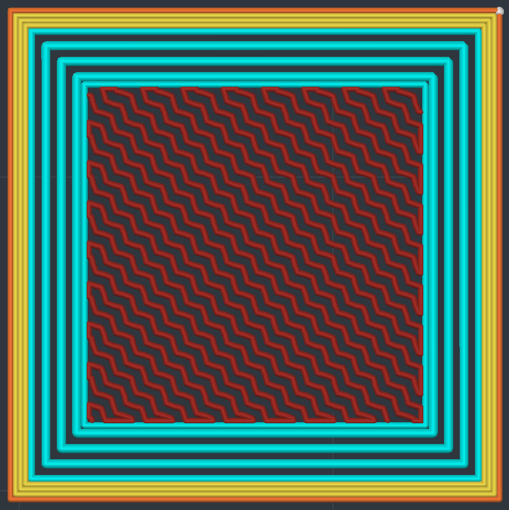
Odd layer
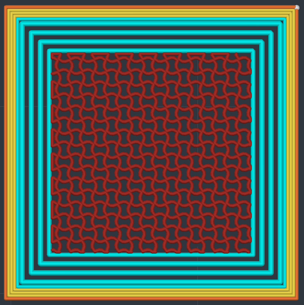
Even layer
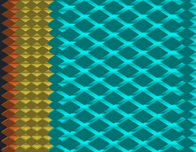
Cross-Section
The cyan interlocking beads are generated adjacent to the object's perimeters. Interlocking is feature-aware and reduces flow when printing over other feature types to avoid overfilling the area. This is visible at the bottom of the image where interlocking begins the pattern over solid infill.
Three Flow Tiers
Not every shell gets the same extrusion rate. Interlocking uses three flow levels that alternate position between layers:
- 100% flow - Normal width bead. Sits at one edge of the interlocking zone, adjacent to the last regular perimeter.
- ~146% flow - Boundary bead. Slightly wider to align with the 100% bead on the opposite layer, keeping inter-shell gaps uniform.
- 200% flow - Full compression bead. Fills the gap between shells on the layer below, creating the interlocking bond.
On odd layers, the 100% bead is outermost and the boundary bead is innermost. On even layers, they swap. The middle shells are always 200%. This ensures every gap gets filled from both directions across two layers.
Interlocking is volumetric flow aware. Print speed automatically adjusts to maintain constant flow based on your perimeter settings, regardless of bead width.
Settings
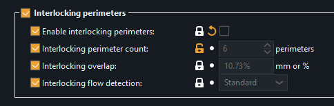
Enable interlocking perimeters
Master toggle. When off, all other interlocking settings are ignored and the part slices normally.
Interlocking perimeter count
How many interlocking shells to generate adjacent to the regular perimeters. Default is 5. Minimum is 3 (below that there isn't enough room for the alternating pattern to work). More shells mean more of the part's interior is interlocked, but leaves less room for sparse infill.
Perimeters while interlocking
Lets you reduce the regular perimeter (wall) count on layers where interlocking is active. For example, if you normally print 4 walls but set this to 2, the interlocking layers will only have 2 regular walls, giving the interlocking shells more room. Set to 0 (default) to keep your normal wall count.
Solid layers above / below
How many layers near top and bottom surfaces to exclude from interlocking. Default is 3 for both. Near surfaces, the interlocking pattern could interfere with solid fill, so these settings create a buffer zone where only regular perimeters are used. This uses a visibility walk that tracks exactly where surfaces begin and end, so the transition is precise.
Interlocking overlap
Controls how much adjacent interlocking shells overlap each other, just like the perimeter overlap setting for regular walls. Default is 10.73%. Increasing it pushes shells closer together for tighter bonding. Decreasing it spreads them apart.
Interlocking flow detection
Controls how precisely interlocking flow boundaries are detected. When the feature directly below an interlocking bead changes from interlocking to a different feature type, the flow rate must adjust. This setting determines how frequently those transitions are checked along the toolpath. Options range from Precise (1mm) to Minimal (8mm). Standard (2mm) is the default. If flow isn't reducing when feature types below it change, try Precise.
What It's Not
Interlocking perimeters are sometimes compared to "brick layers," but they are fundamentally different. Brick layers alter bead height within a layer using Z-axis manipulation, creating half-height and full-height beads. In every slicer that offers them, brick layers run as a post-processing script that modifies G-code after slicing. Interlocking perimeters are a native perimeter feature type built into preFlight's slicing pipeline, exclusive to the Athena perimeter generator. All beads are printed at constant layer height with no Z-axis manipulation. The bonding comes from material compression through spacing variation in the X/Y plane, not geometric stacking through height variation.